SimpleRDC 🔗
This is a step forward in making wireless communication more easy and viable for extremely small systems. There already exist a number of protocols for low-power wireless. Most of them are quite complex and hence use much RAM and ROM which makes them unfeasible for the Launchpad and similarly constrained systems. This is a simple yet efficient radio duty-cycling protocol for Contiki that achieves 3% idle listening duty cycle while allowing for an average 65 ms latency with no prior contact or synchronization.
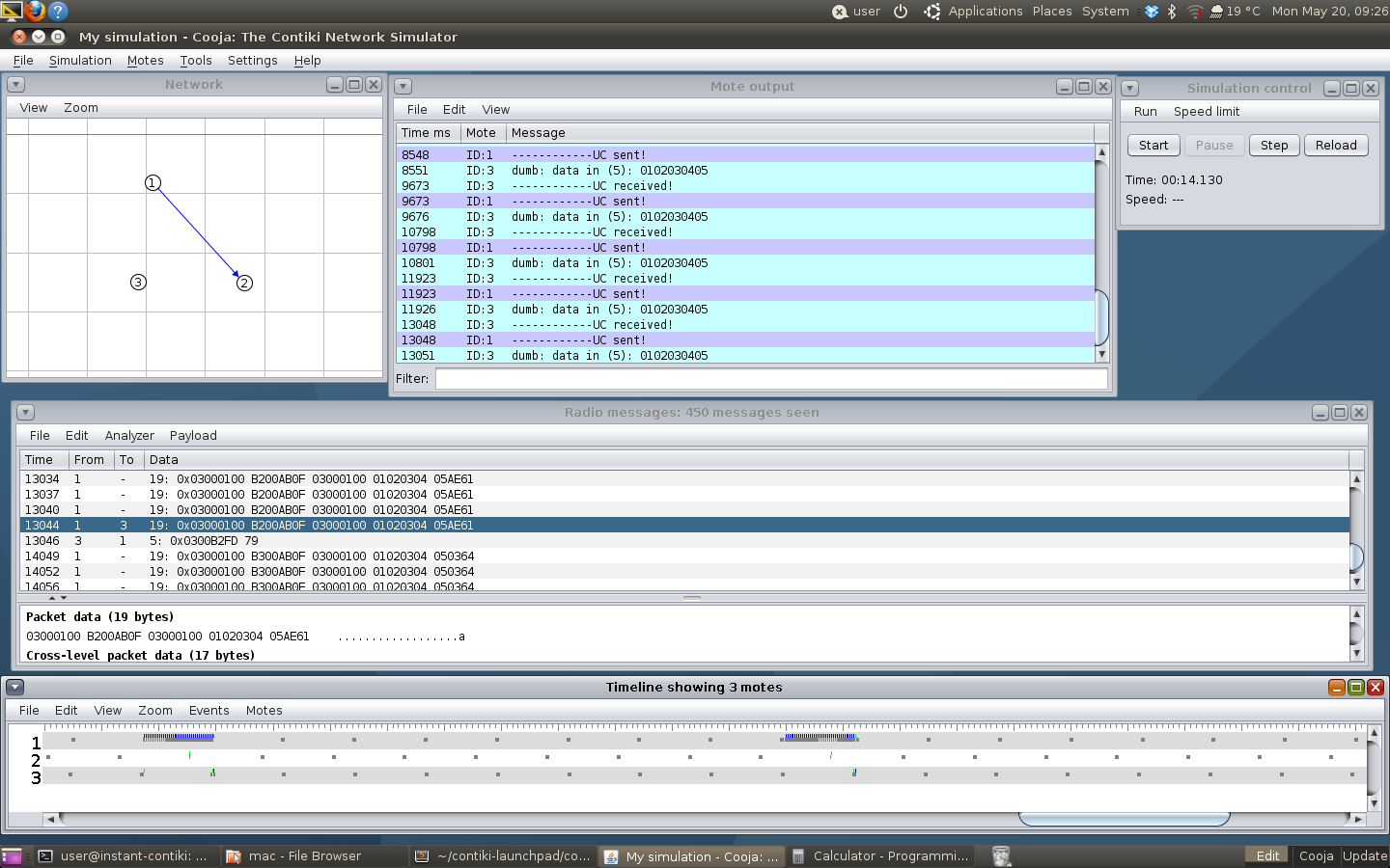
Three nodes running SimpleRDC in the Cooja simulator, one of them periodically transmits. Grey means radio is on, blue means that it is transmitting and green that it is receiving (red, not in the picture, means interference, ie it senses something but cannot make out what it is). In the "Radio messages" dialog box you see the actual bytes sent over the air. Here, just a simple hex 0102030405 and some frame headers. The ACK of 5 bytes contains the address, a serial number and two bytes CRC footer added by the radio driver. The node serial output is seen in the "Mote output" box.
Why do we need to do this? Well, it's an application-specific question and at least for battery-operated (or similarly, energy scavenging) systems, it's expensive, cumbersome, and in some cases infeasible to change batteries in situ. Or rather, it all comes down to $$$. The microcontroller in this case, which is a really low-power microcontroller, is not the most energy consuming component in the system. The radio is.
The msp430 uses about a milli-ampere in operation, ie about 1-3 mW. A typical 802.15.4 ISM radio on the other hand needs ca 45-60 mW when transmitting and 60 mW when receiving. This is true for both sub-GHz and 2.4 GHz radios. You might ask why it's more expensive to receive (or listen)? To receive, the radio must have a crystal oscillator running, radio signal amplifiers and filters and logic running in order to find any signal in the medium. This takes a lot of power in comparison. So, we try to keep the radio off as much as possible.
SimpleRDC, as it's called, builds on protocols such as ContikiMAC and X-MAC but makes away with lots of the complexity. It's also quite similar to the Thingsquare Drowsie RDC protocol and part of the subset of RDCs we call LPL, or low-power listening, in contrast to eg LPP, or low-power probing.
We periodically wake up and listen for a while before going to sleep to save energy. To transmit to a neighbor, we repeatedly transmit the frame for an entire sleep period and a little more. This way, we should be able to hit the wake-up of the neighbor. In ContikiMAC, we learn when the neighbors wake-up and can time any outgoing messages to the wake-up, thus saving time, energy, and bandwidth. SimpleRDC has not support for this out of the box due to the RAM constraints. Neighbor tables take a lot of space.
If we want to transmit a broadcast, ie to any neighbor that may hear the message, we transmit for a sleep period plus some guard time, and turn off the radio between each transmission. With unicasts, ie one specified destination, we can optimize this a bit. If the receiver tells us when it has received the message, we can end the transmission train early. Thus, we keep the radio on and listen for this short acknowledgment (ACK). We can tune this to send and recieve ACKs quickly, thus reducing time between transmissions, and as a byproduct of this reduce the on-time in each wake-up.
Simulations 🔗
Let's compare a broadcast with a unicast.
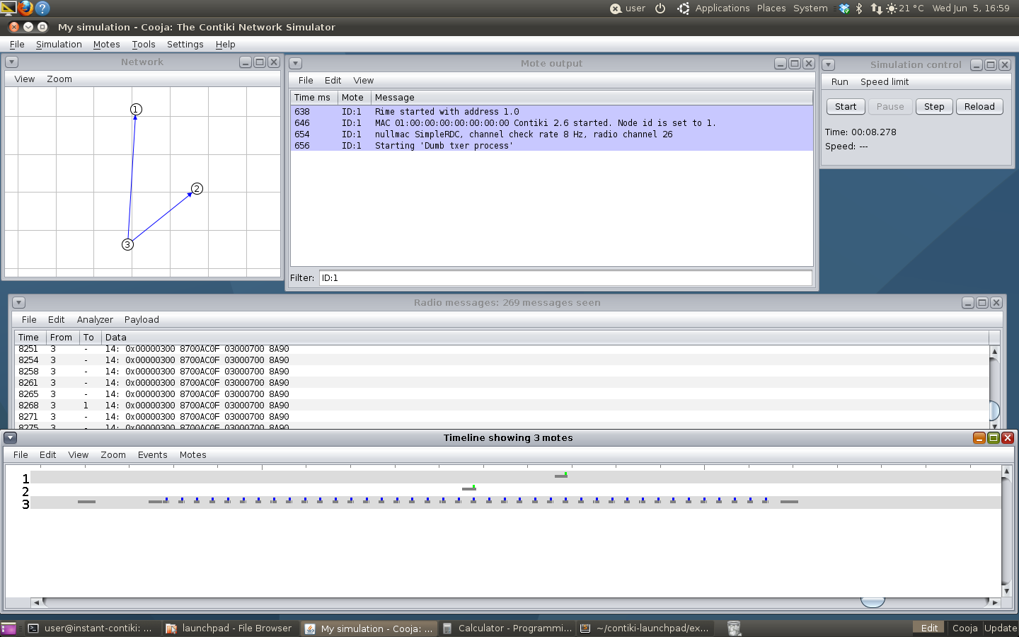
Being a broadcast, the sender do not need an ACK and turns off the radio in between transmissions. Note that all the blue bars are transmissions, the same packet being transmitted over and over again.
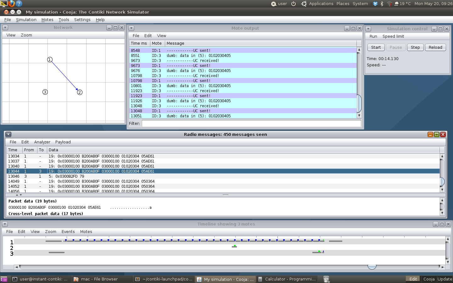
The unicast on the other hand keeps the radio and hopes for an ACK. When it receives it, it can terminate the transmission train. A bystander that receives it just drops it and goes back to sleep.
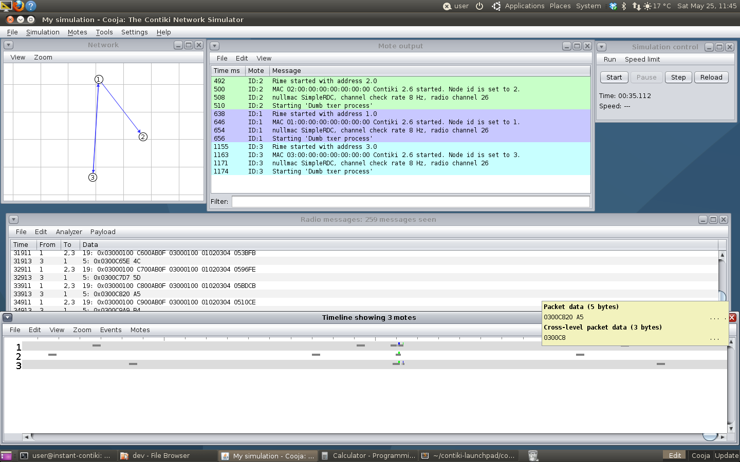
If the sender is lucky, it starts transmitting at just the right time and can finish very early, here after just one transmission.
Sniffing the SPI 🔗
Simulating the RDC is very convenient when developing as you can just do a reload and replay the same scenario over and over again. It's also fast, this was running at 10-20 times realtime. However, to validate this working in real life too, I looked at the SPI communication between the microcontroller and the radio transceiver. This was done with a Saleae Logic 16 logic analyzer, probing the pin header on one of the Launchpads when running a simple application. On the top four channels we see the SPI: MISO, MOSI, CLK and CS. Then, we see the GDO0 pin from the radio, configured as staying high while receiving or sending, and low otherwise (ie off or simply listening). Channel 5 is an LED toggling when we have sent something.
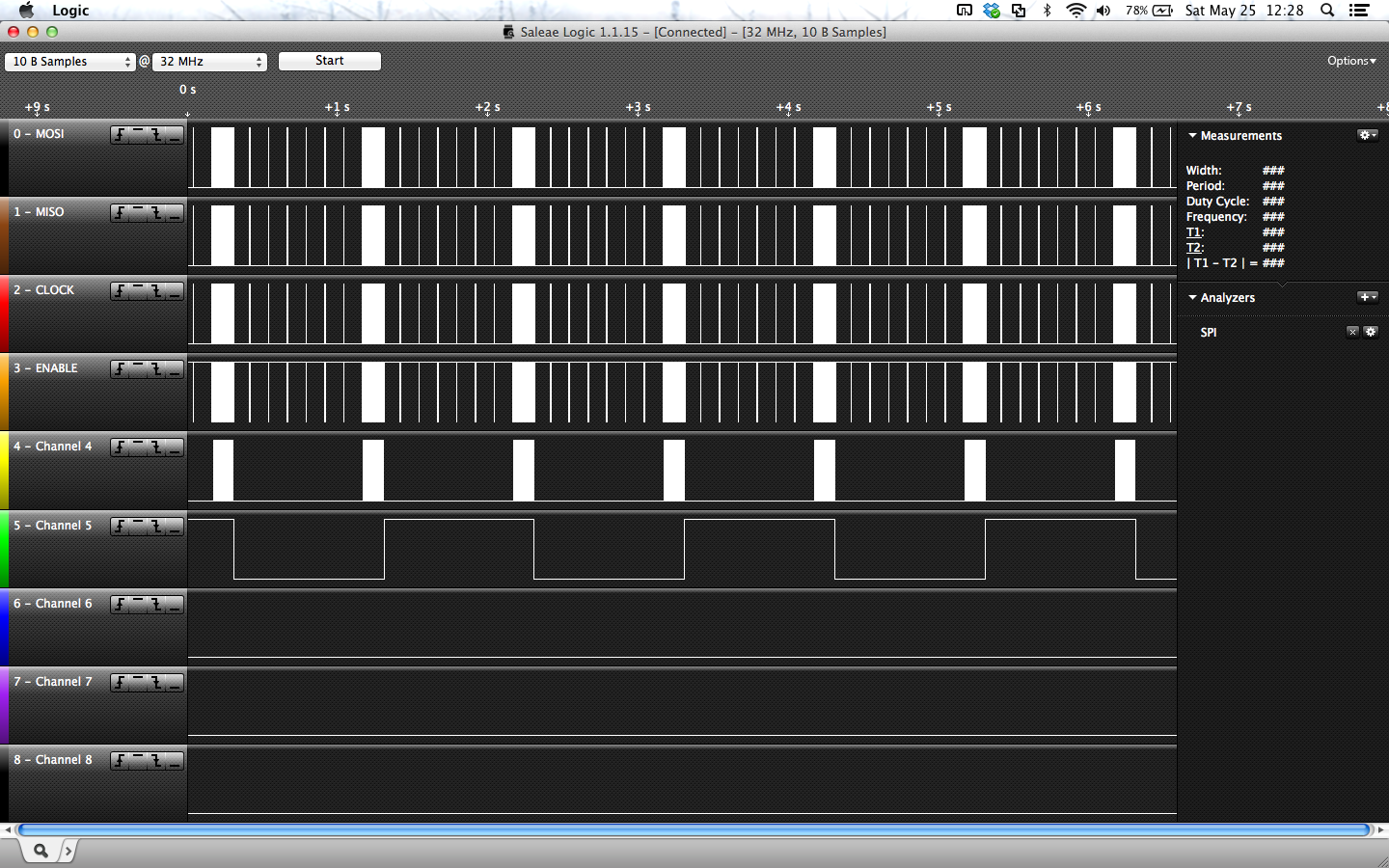
We here see the SPI communication of a device doing channel sampling every 125 ms (the narrow bars) and one a second transmit a message (the wide bars). Each bar is actually many SPI transactions for the microcontroller loading the radio with a packet, issuing commands, polling it for status etc.
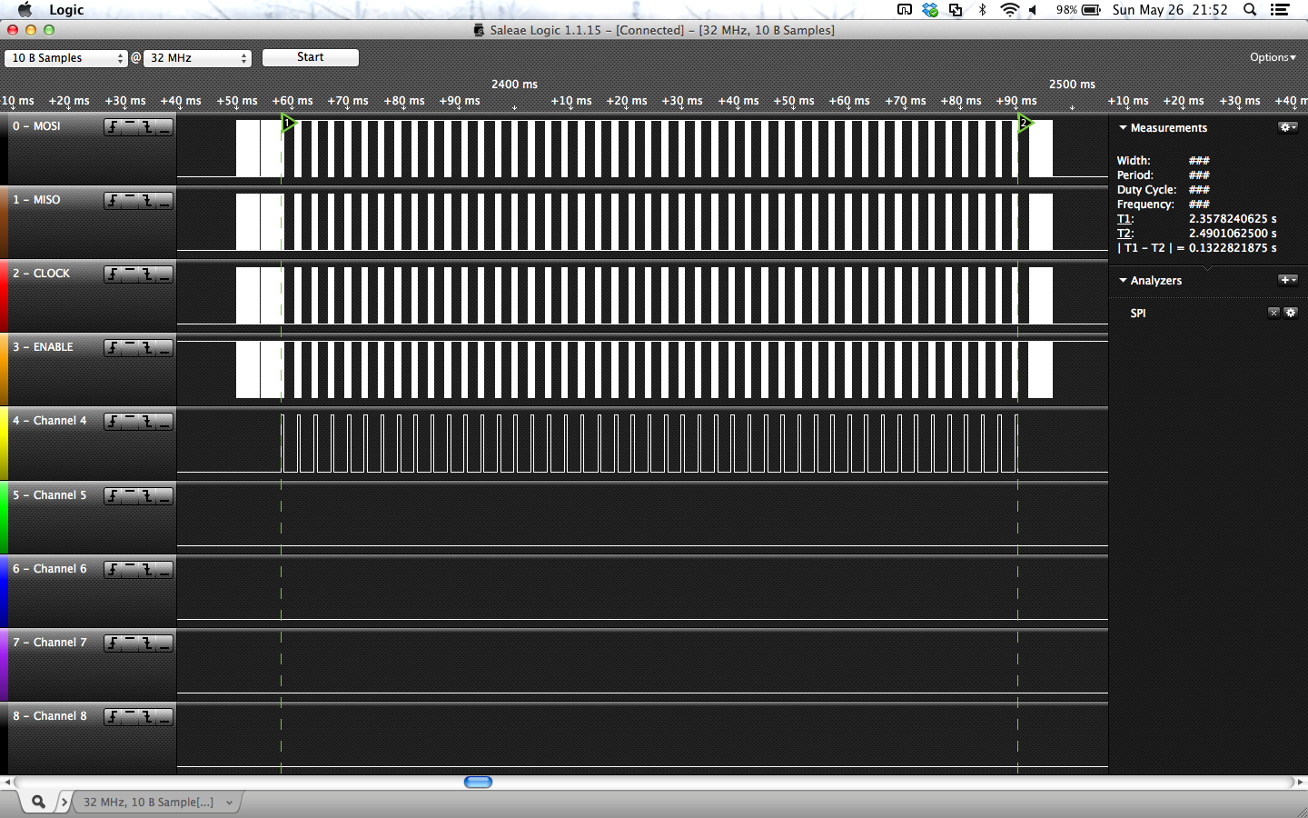
Here we zoom in on one broadcast. We see that the radio first performs a CSMA-CA (Carrier Sense Multiple Access, Collision Avoidance) to make sure that it is free to start sending. If we receive anything during this CSMA, we drop the packet. Then, we perform a number of transmissions, turning off the radio in between. At the end, the radio channel sampling is due so we do that too.
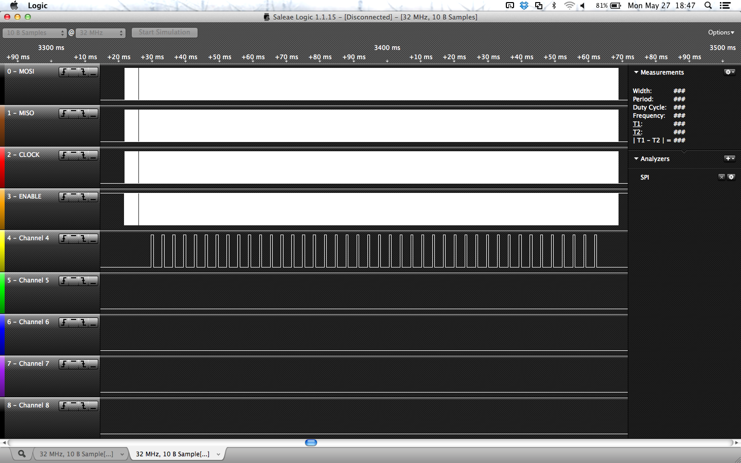
In contrast, unicast transmissions wants an ACK so the radio is kept on and constantly being polled. The tranmission in the picture was not ACKed so we quit after a while.
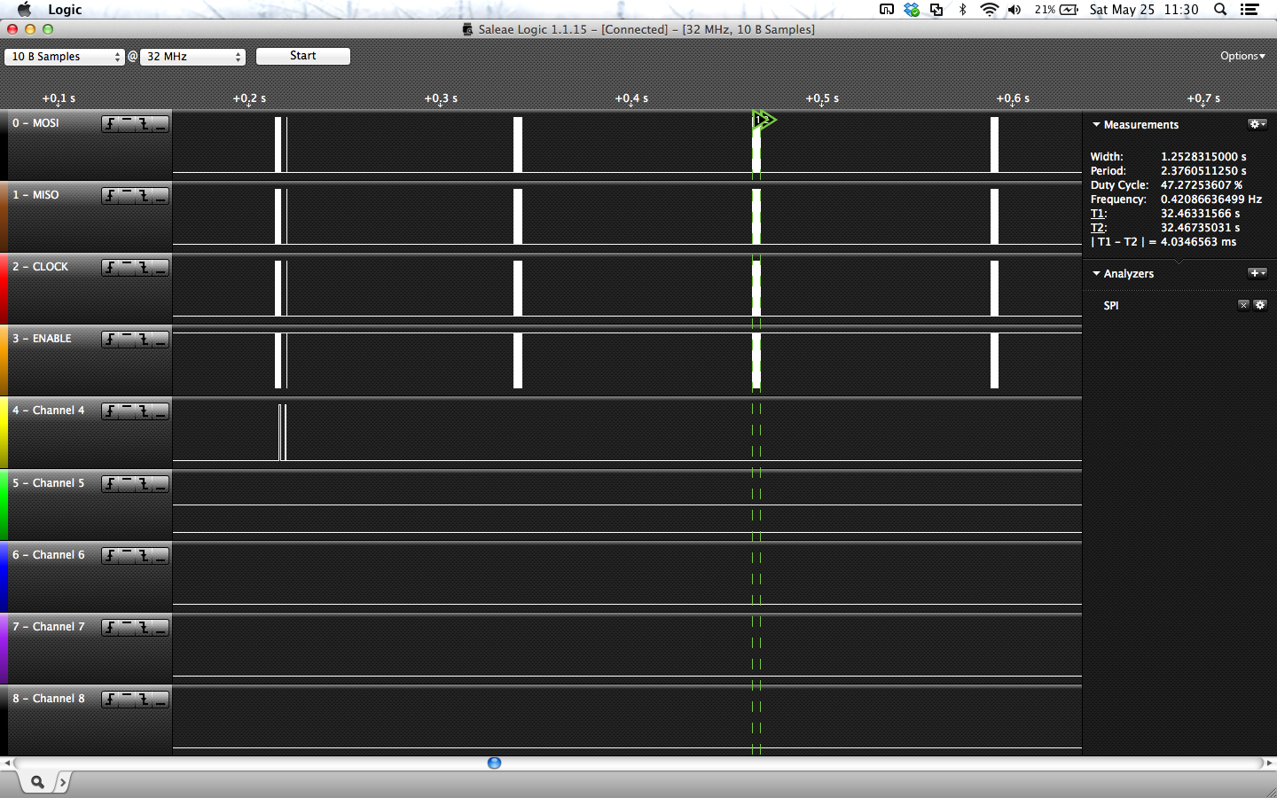
On the receiver end, we see dramatically less SPI transactions. This is a few channel samples, and during the first we received a packet that is destined for us so we send an ACK and go back to sleep. The sender would (hopefully) receive this ACK and can then turn off.
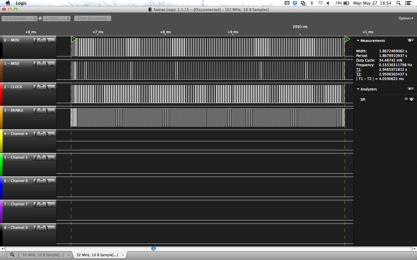
This is a 4 millisecond channel sample. First issue the command to turn the radio on, wait for it to start listening after the crystal has stabilized and then poll the radio to see if we get anything. If we do, we turn the radio off. Here, we got nothing.
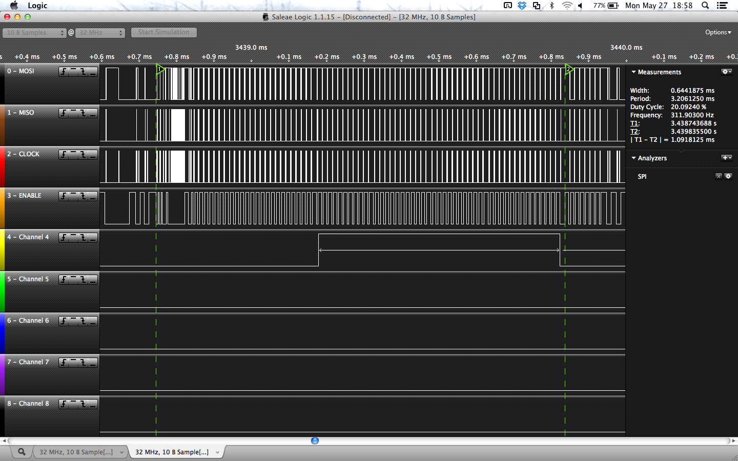
A single transmission: load the transmission FIFO buffer in the radio, then issue the "transmit" command, wait for the transmission to end. The bump on channel 4 is the GPIO on the radio being high during the transmission, so we can see and measure exactly how long time this takes (0.64 ms). What we see here is basically corresponding to one of the blue bars in the Cooja simulation screenshots earlier.
Bring out the 'scope 🔗
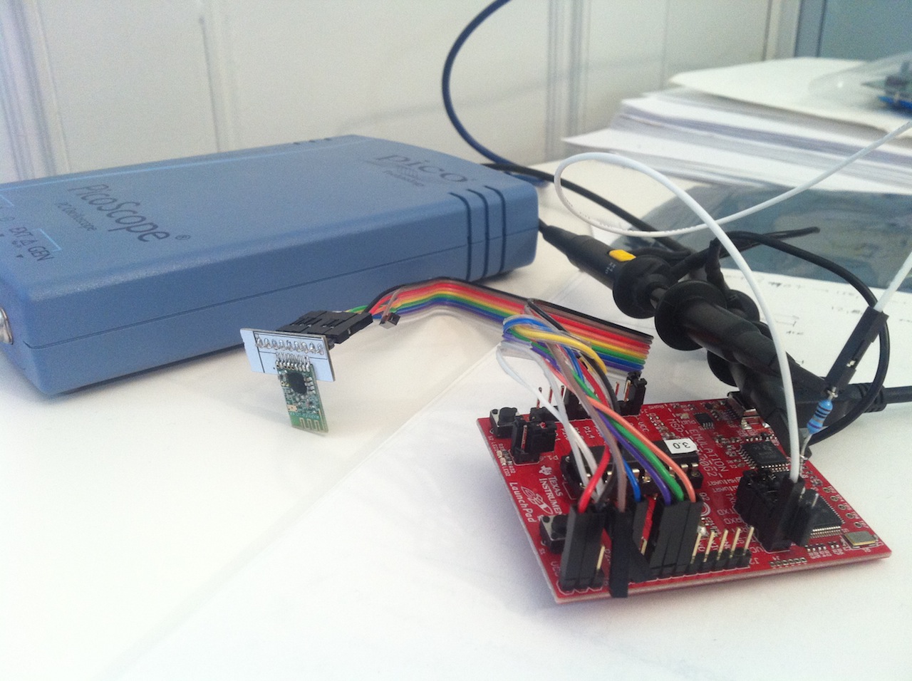
So far, we have simulated it so we had a pretty good understanding of how it works, checked the SPI so we know the proper commands are being issued, the timings line up with what we expect from Cooja etc. But, even now we would like to have more proof that it works as intended. There may still be bugs that end up consuming lots of power without it showing up on either Cooja or the Logic. Time to use an oscilloscope and measure the power consumption. I used a Picoscope 3206B dual-channel, 200 MHz bandwidth, 8-bit oscilloscope measuring the voltage drop over a shunt resistor of 10 ohm, 1%, in series with the Vcc that powers the microcontroller, the Launchpad, and the CC2500 radio.
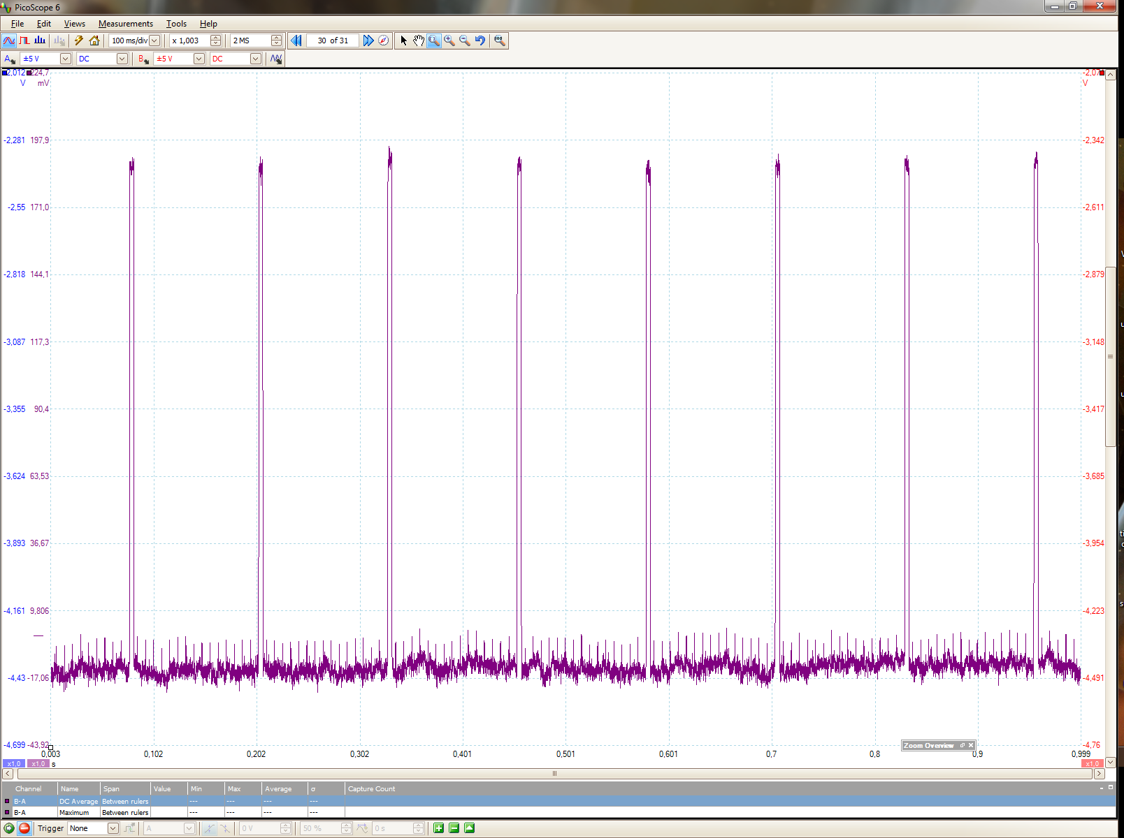
We see very clearly the wake-up channel samles every 125 ms showing up as spikes in the power consumption. Notice the scale being in mV, and not really properly offset to zero. The noise is also there. To put things into perspective, we also see the 128 Hz microcontroller wake-ups. The msp430 sleeps most of the time, in LPM3, but wakes up every 7.8 ms to see if there is any event in Contiki pending (such as timers). The power consumption is very low and runs for a very small amount of time. The energy used is the area under this plot so we see the energy used for one single channel sample is vastly larger than several seconds of mcu time. Thus, it is often very beneficial to massage data before sending it, if we can reduce the amount of data being sent. IIRC I calculated 1 sent byte (once, on CC2420 at 0 dBm) to correspond ca 2000 cycles on an msp430 @ 16 MHz.
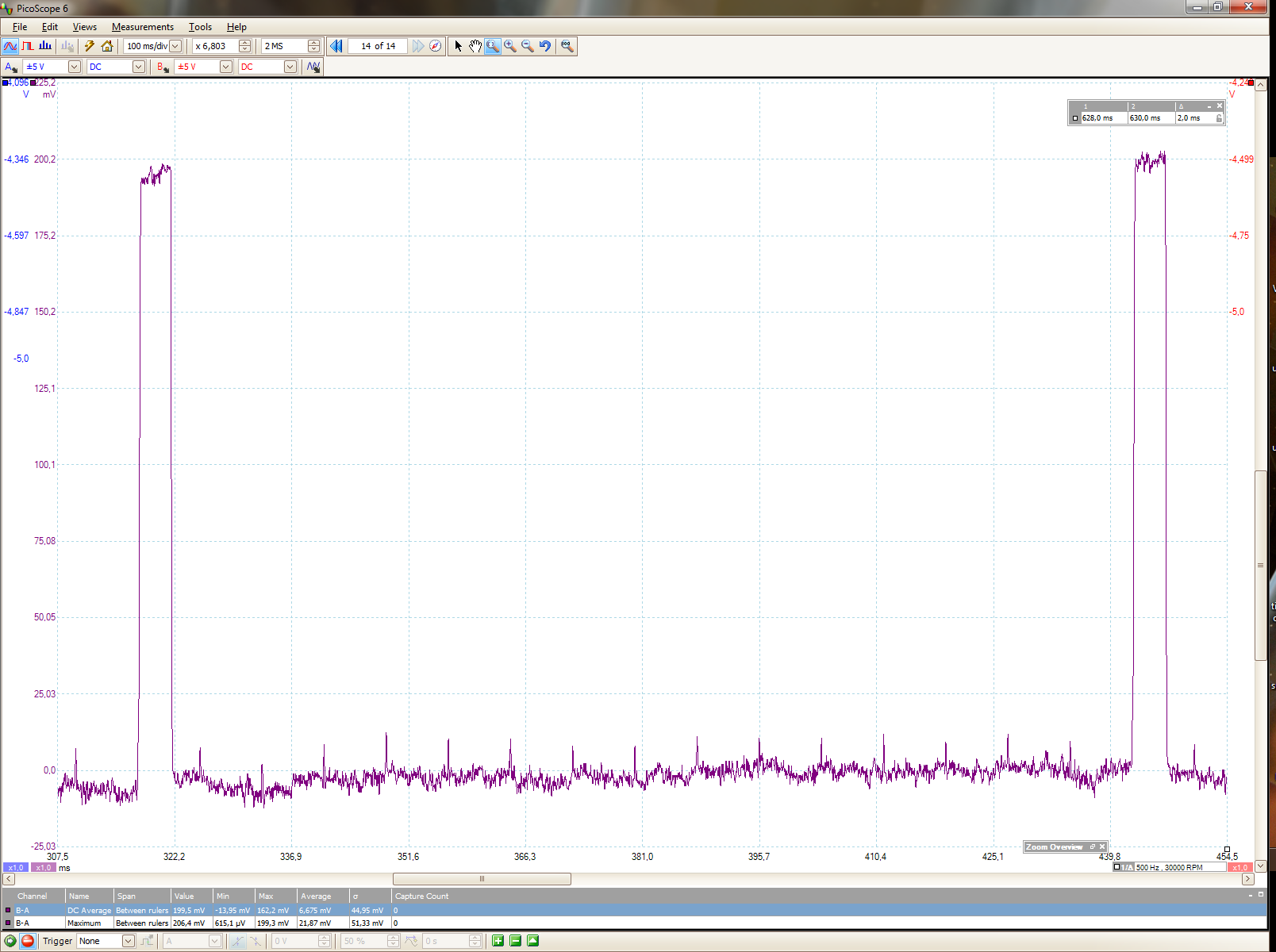
Closer look at channel samples, and we again see the mcu waking up. The current draw in mA is here approximated as taking the voltage drop, divided by 10, so we see approx 20 mA when listening, which checks out well with the datasheet.
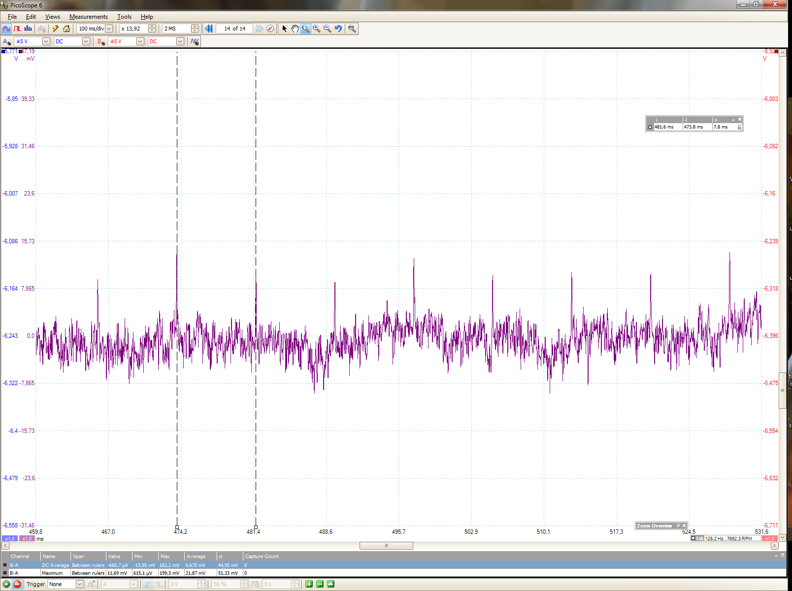
The mcu wake-up power peaks at 128 Hz. There is not much being done in the background really.
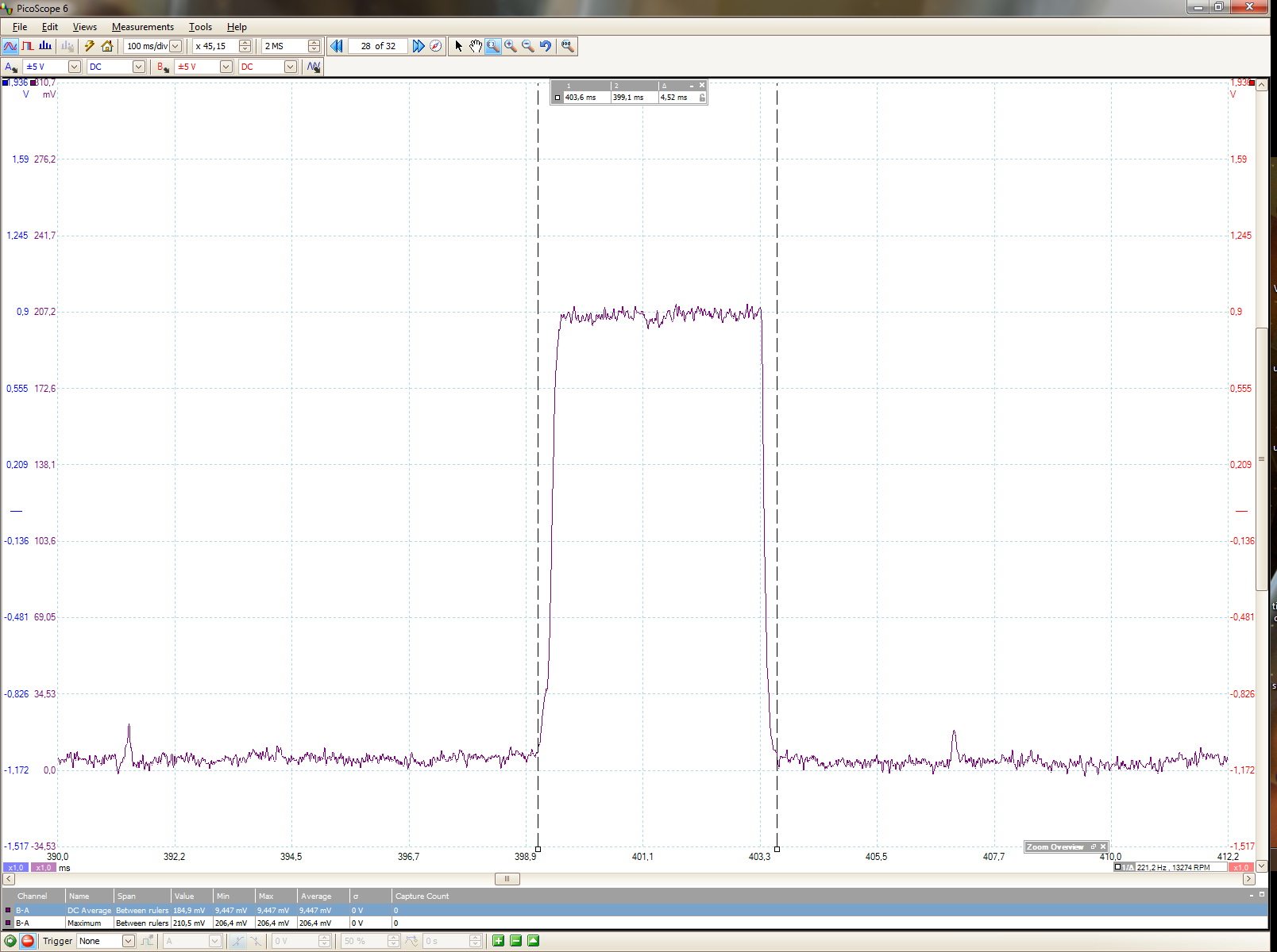
Zoom-in on a channel sample. 18.5 mA for 4.5 ms, as it takes a little while for the crystal to stabilize.
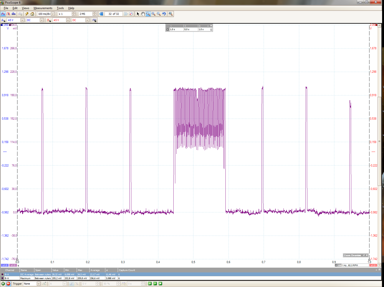
A unicast transmission and some channel samples.
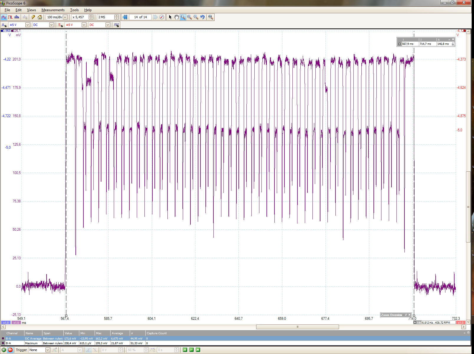
A full unicast transmission train of individual transmissions. Notice how the radio is kept on between transmissions, and that the transmission is not ACKed so the entire train is transmitted.
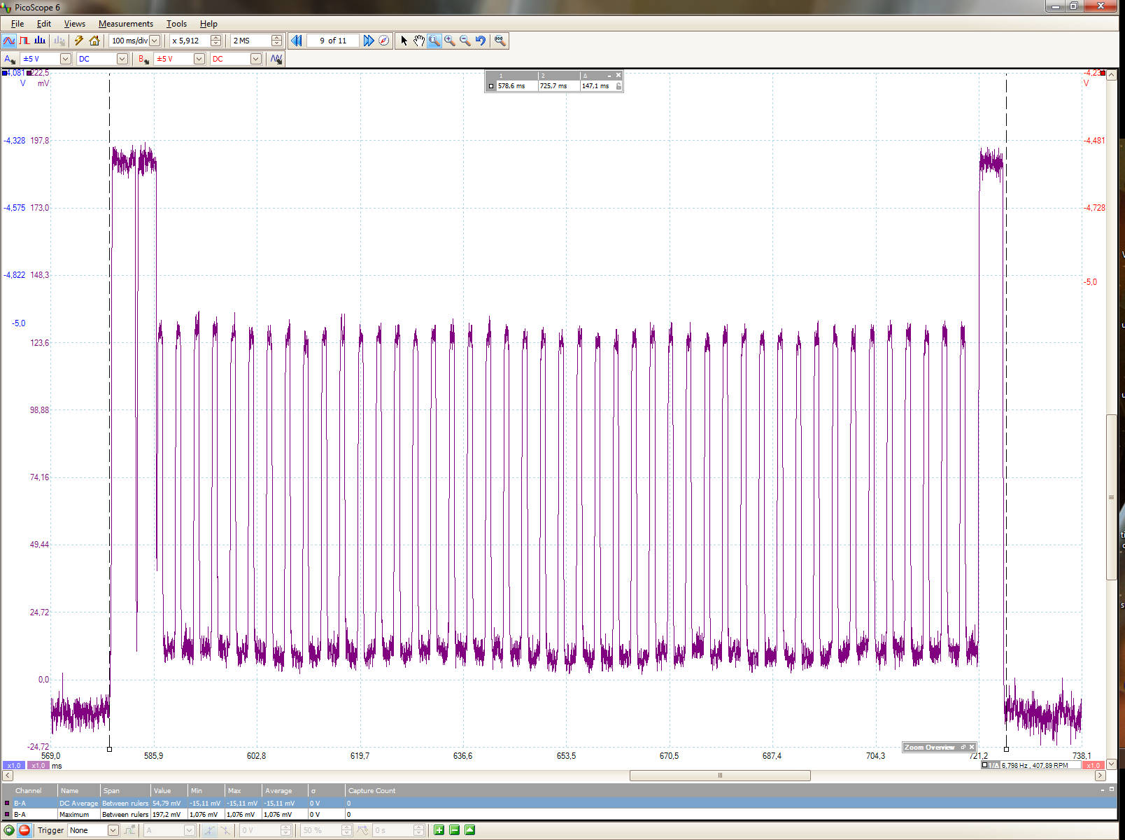
A full broadcast transmission.
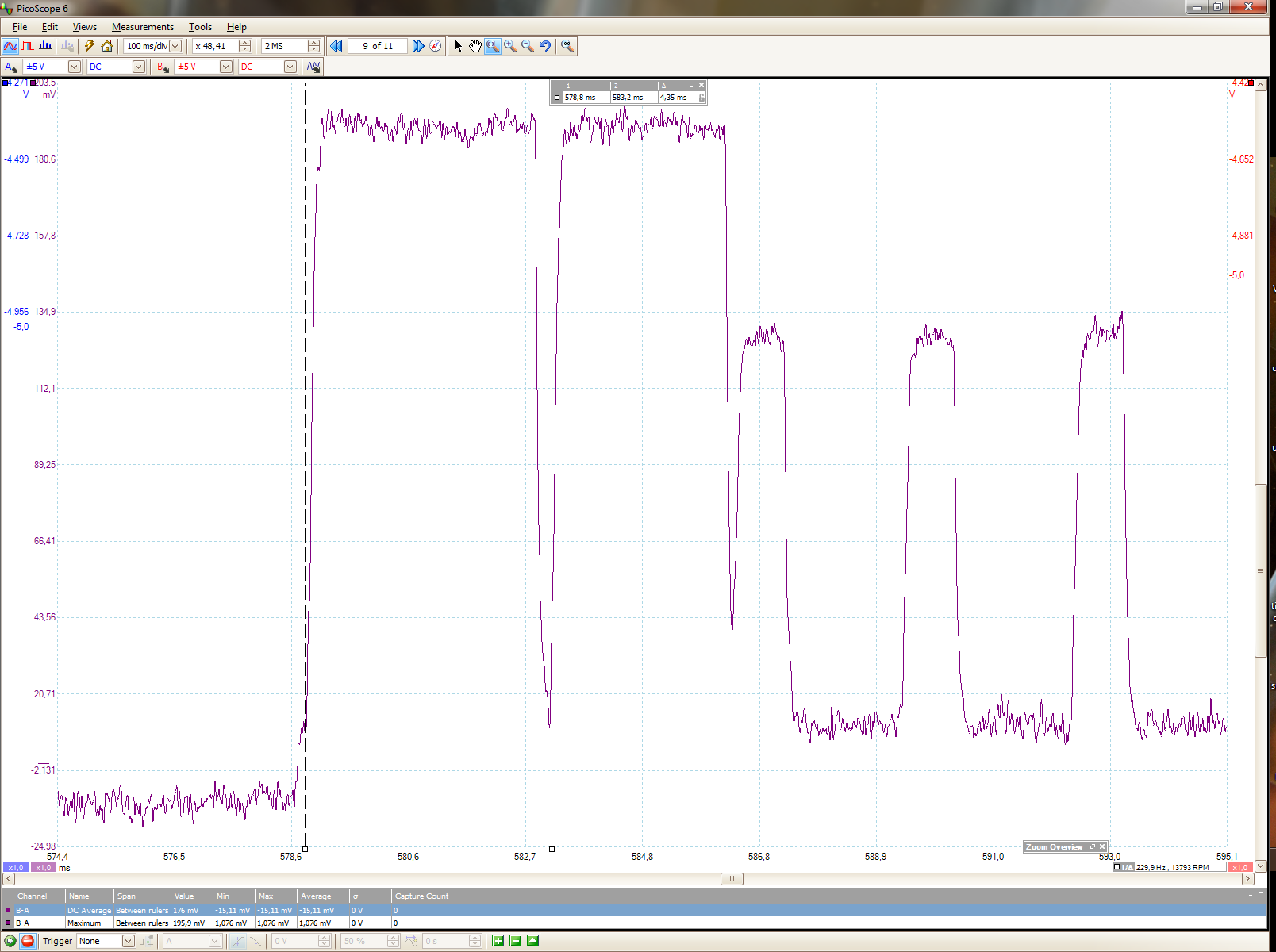
Close-up of the start of a broadcast. When waking up, we see that it is time to perform a channel sample, then next up in the Contiki event queue is the application process which initiates a transmission. We see the CSMA and the first few transmissions. The radio is off in between, it all looks good.
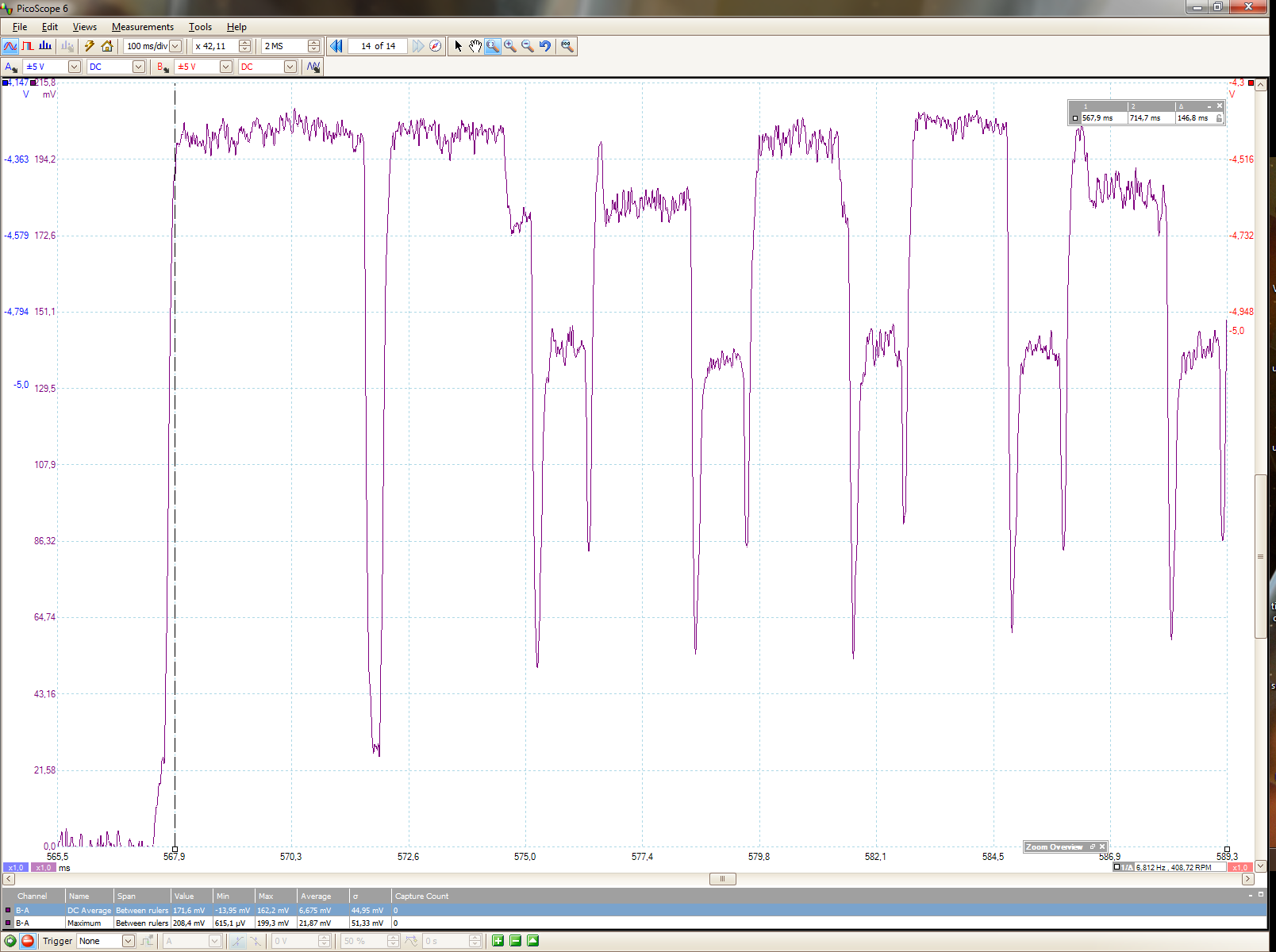
Close-up of the start of a unicast. Same as the broadcast, but we see how the radio is kept on between transmissions. Notice how the power consumption (proxy as the voltage drop here) is higher when listening than transmitting as we need to keep amplifiers, filters, logic etc running and searching for the pre-amble of a packet.
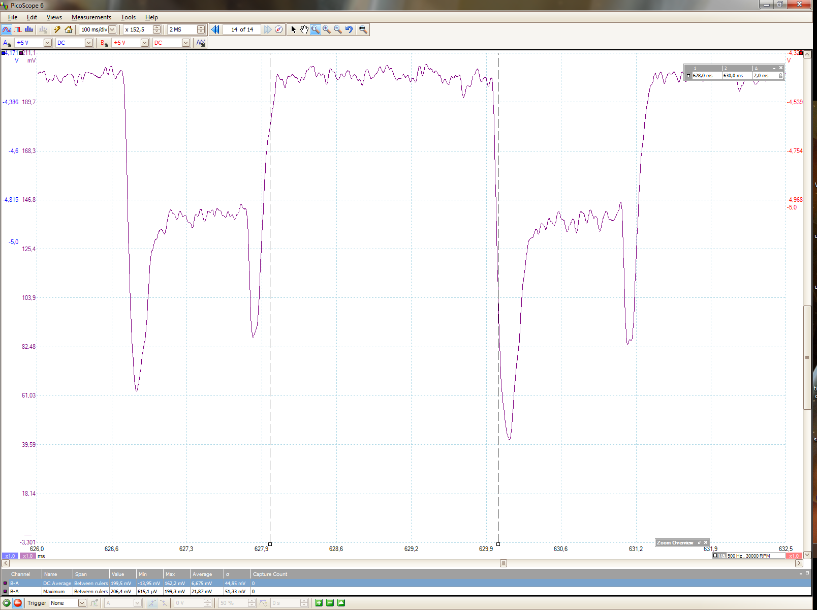
One transmission and listen for ACK. We measure the width of the listen to 2 ms, which is precisely what we expect it to in this configuration of SimpleRDC.
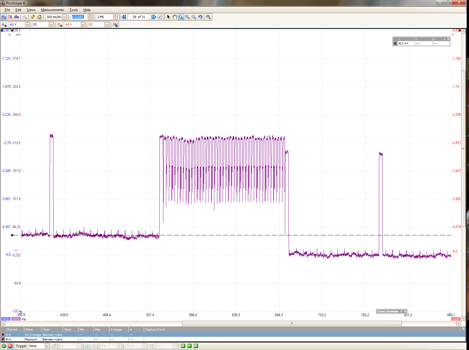
In this image we see the LED turning off after having transmitted, lowering the baseline power consumption by ca 3.7 * 3.3 = 12.21 mW. The LEDs (this was the red) seems like low-power LEDs. Usually normal red LEDs require about 20 mA -> 60 mW, as much as the radio.
Verdict 🔗
So, with SimpleRDC we have a radio duty cycling layer that needs no setting up or synchronization, while still having a 3% idle listening duty cycle and 65 ms average latency. We have verified it with simulations, looking at the radio to microcontroller SPI communication, and at the power consumption with an oscilloscope. And, we can run it on a 512 byte RAM microcontroller - while still having space for an operating system, drivers, and applications!
Can it be made smaller? Not much, if any. We have already ripped out pretty much all functionality that is not strictly needed. I tried to reduce to depth of the call stack to minimize RAM usage. There is only the packetbuffer statically allocated (part of Contiki).
Can it be more efficient? Sure! If we can reduce the time from receiving a frame to sending the ACK (including downloading the received frame, checking address, loading the ACK into the radio, and the transmission time), then we don't need as long wake-up checks (currently 2 ms). Another approach is reducing the channel check rate to, say, checking every 500 ms instead of 125 ms. Then we get a duty cycle of ca 0.75% but an average latency of 250 ms and reduced bandwidth as there is more traffic per transmission. However, depending on the application, this might be the right way to go.
Post scriptum 🔗
I noticed a bug while measuring with the oscilloscope. It's now fixed, but I didn't notice it before, with the logic or in simulations. The radio did sometimes end up stuck in an almost-rx-state, as seen by the power consumption. It was always from a channel sample, so I think that it recieved a corrupt frame (or noise) with a very large length-byte, putting the radio in an erronous state (the errata Rx FIFO overflow seems like a likely culprit).