HPDL-1414 clock 🔗
After having ported Contiki to the Launchpad, I was eager on doing something with it. I built this simple clock with a vintage HPDL-1414 "smart four-character 16-segment alphanumeric" display and a msp430g2553.


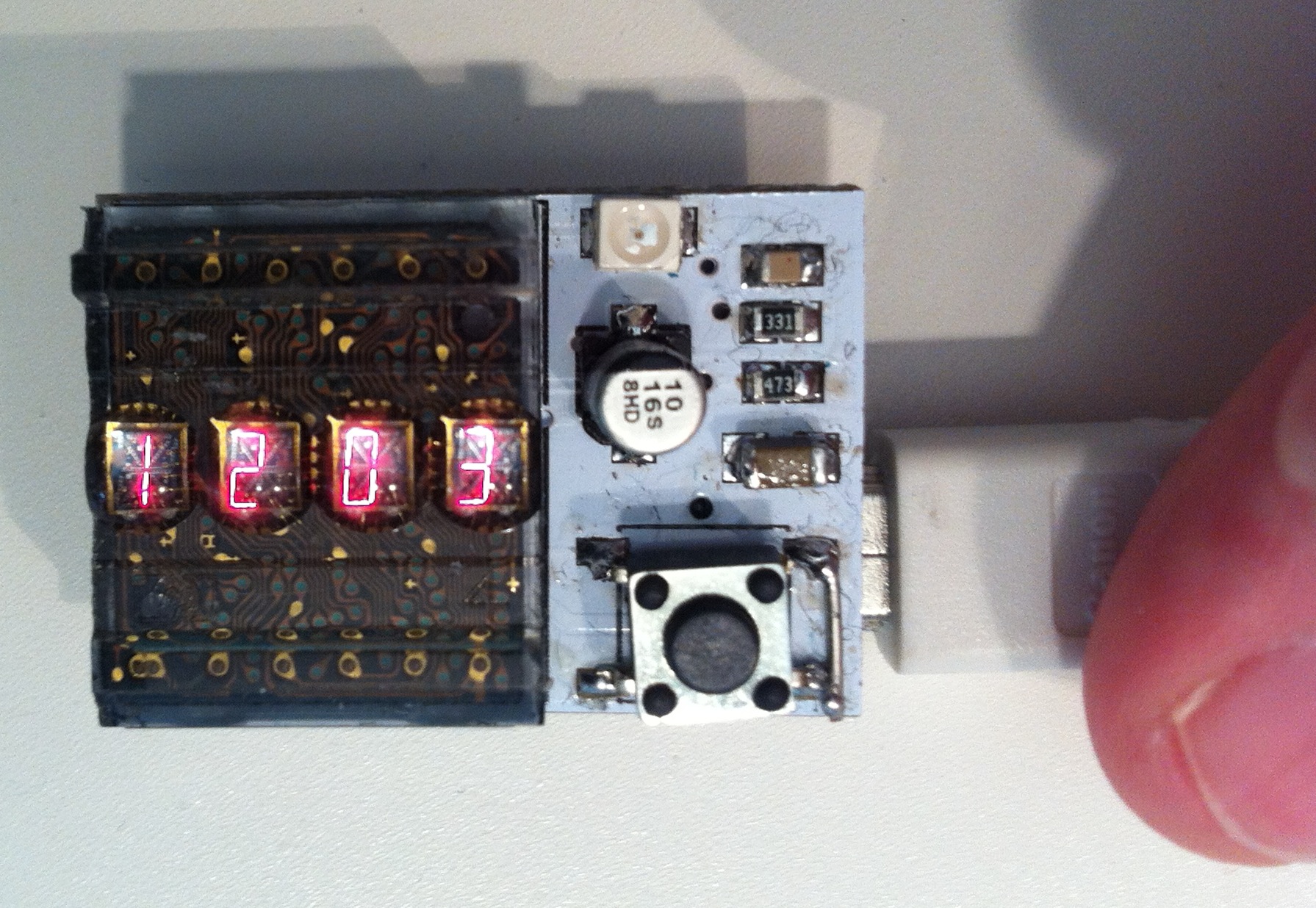
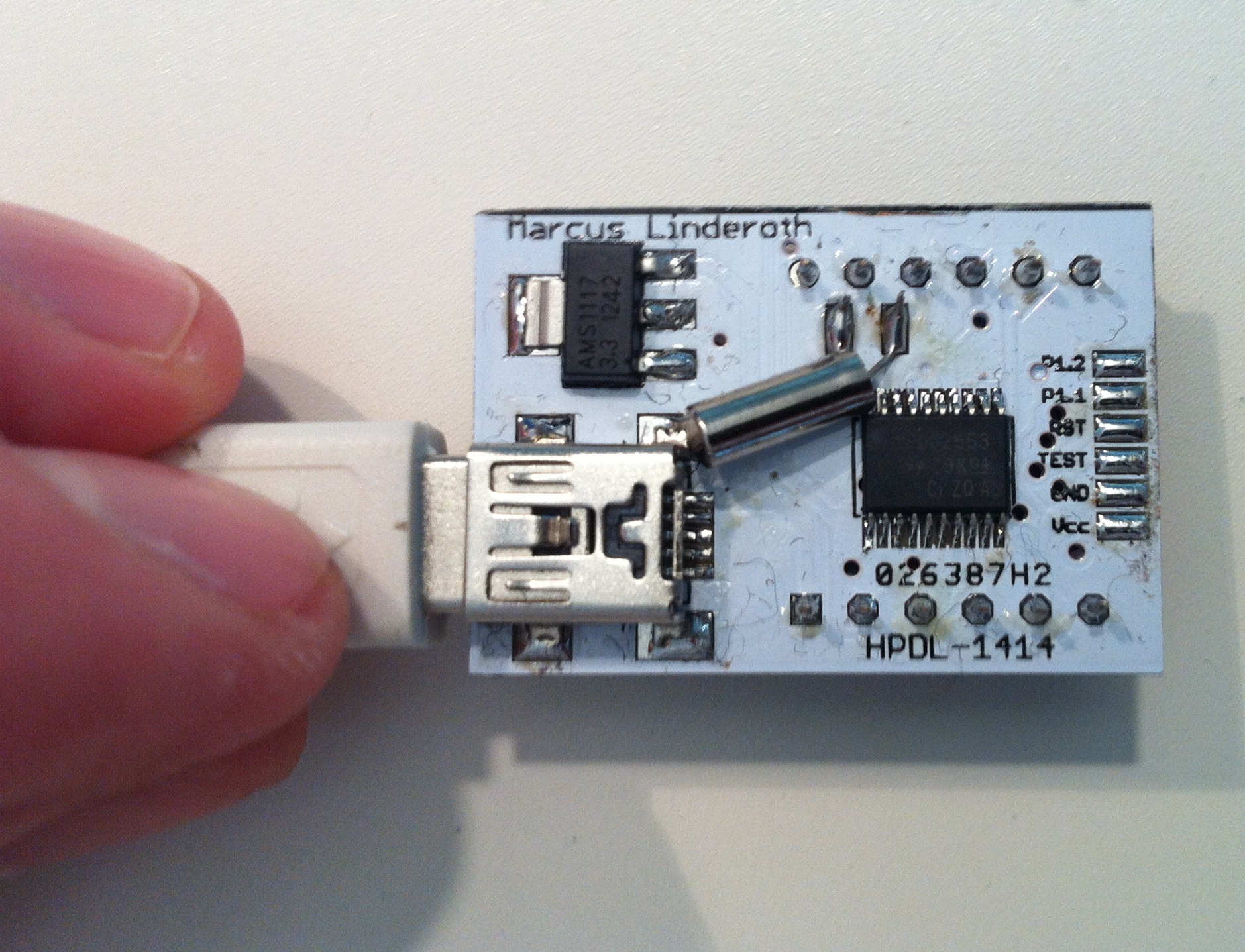
The soldered clock from above and bottom. There is a lot of solder flux residue, and lots of small black pieces of fabric from my bag, which lessens the appeal of the white solder mask. Quite nice though. Now I should make one that runs off batteries instead (the HPDL-1414 can run from 3 V but looks a bit more faint then). The eagle-eyed may notice the work-around on the button. Turned out the Eagle footprint I made was wrong, connecting the wrong two legs.
Video bootup 🔗
This video shows the clock booting up and me setting the time.
The clock is really simple. It's powered over USB, with an AMS1117-3.3 LDO linear voltage regulator that drops the input voltage to a handy 3.3 V for the msp430, but the HPDL-14144 still gets 5 V directly from the USB Vcc, to keep the display output nice and bright. Fortunately, the display is compatible with 3.3 V on the IOs. There is a button used for setting time, and a GPIO used for alarm (eg a vibrator) or as now, a LED that blinks every second.
The HPDL-1414 display has two pins for choosing what character position to set, and seven pins for choosing what character to set (in ASCII). Supply voltage 5 V but accepts 3 V logic level on the IOs. The characters are 2.85 mm tall red LED magnified with bubble plastic in front of them. This gives them a very characteristic look which is very beautiful.
Here is the replacement part. Here is some information about them from vintage display enthusiasts.
When booting up, the clock goes into demo mode if the button is held for a while, then shows a splash scroller, and finally starts the clock. The clock works just like any other clock. Push the button to set the time, hours first, then minutes. The demo mode scrolls through all the possible characters and shows a nice spinner animation. The clock is running my Contiki 2.6 port to Launchpad, available on Github.
I'm considering using a vibration motor, similar to those used in mobile phones, to buzz every 20 minutes during work hours as a reminder for the 20-20-20 rule to battle eye fatigue. The rule says that you should every 20 minutes, look at something 20 feet (5-10 meters for us Imperial-units-impaired) away for 20 seconds. This is especially important for anyone working by a computer for long durations at a time.


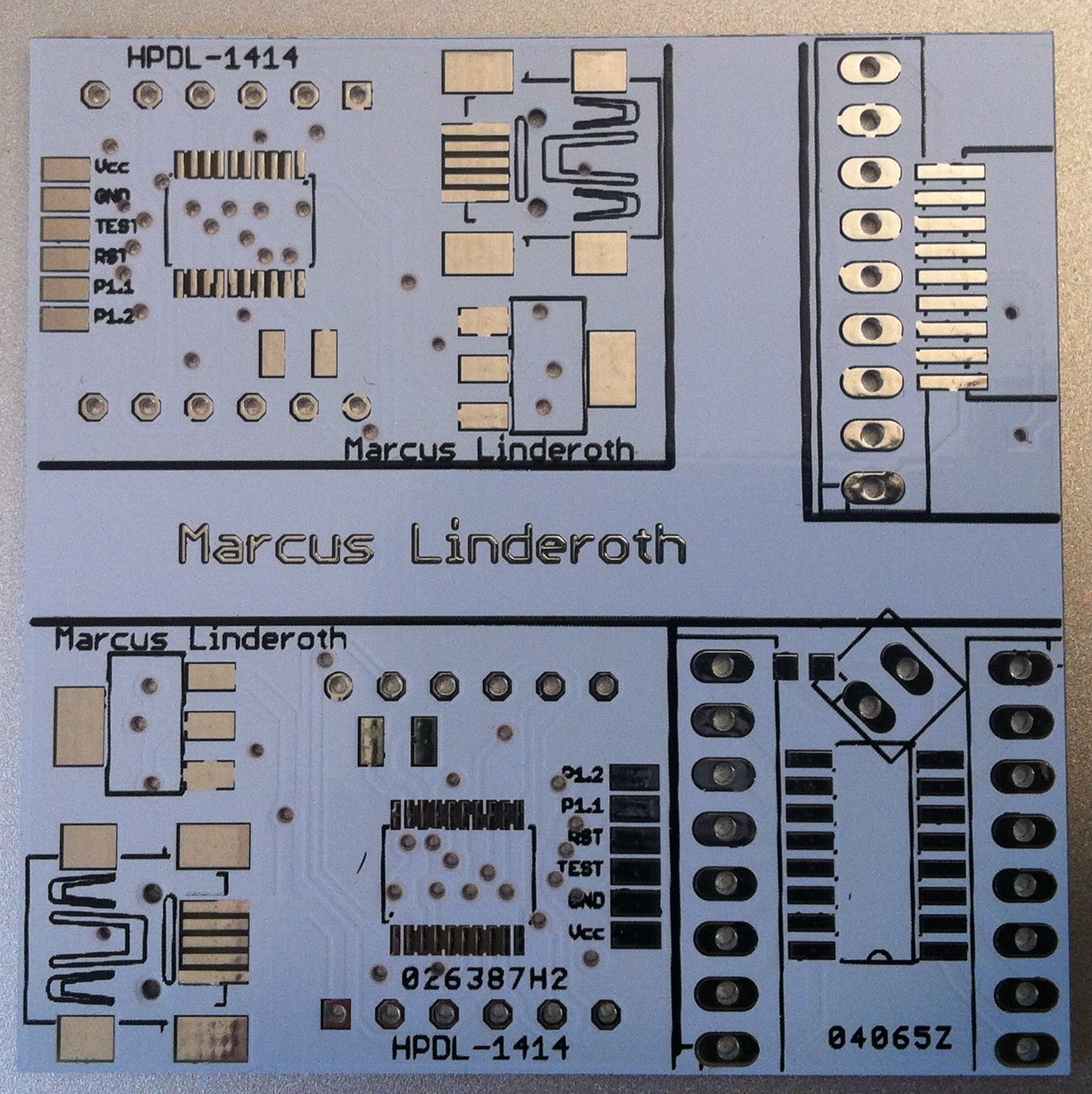
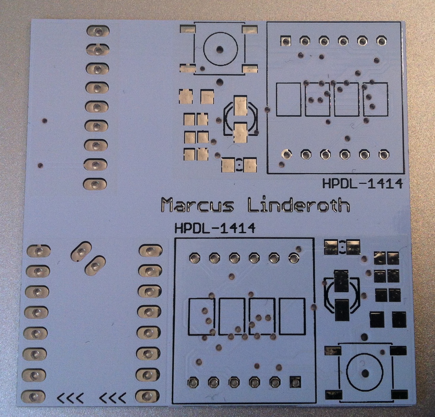
The PCB is a small outline PCB manufactured at a Chinese fab. Ten pieces of 5*5 cm 2-sided PCB with white solder mask and black silk screen for ca 20$ including shipping. The boards were of pretty good quality. My only complaint apart from ahem "user error" (forgot to add the silk screen layer when producing the Gerbers) is that for footprints with small separation between tracks, such as the SOIC MCU pads, or the signal and power pads on the USB connector, they removed the solder mask between pads, increasing the risk of solder bridges. But, considering the resulting boards look good, are cheap, relatively fast (3-5 weeks, don't remember), and actually work, I'm very happy. I designed the PCB, and the library parts needed, in Cadsoft Eagle. The boards seen above is a mix of four boards on a 5x5 surface: two clock boards, one CC2500 radio module breakout board, and a ULN2003A breakout board.
Video demo 🔗
This video shows the clock booting up to demo mode, then continuing to normal boot up.