PLP Jump
The PLP project was a bachelor level student project at KTH (the Royal Institute of Technology), Stockholm. PLP stands for "Play, Log, Predict". The mission was to create something that would make children with weight problems to want to exercise more, and by over time logging exercise levels and other metrics being able to predict things like health and weight with that child. Jump is the name of our result - a two meter by two meter dance floor with upwards shining colored lights and pressure sensitive cells.
The predecessor classes had built a dance mat, similar to the ones you could by at the time and connect to games on the Sony Playstation, but larger and not having to use a screen. We were to follow in their footsteps and build something along those lines but were fairly free to make something different.
What we built was to be evaluated with children from a school that catered to children with mental disabilities and so we were very eager to do a good job. The project group consisted of seven students from different programs at KTH, that all had Mechatronics as major.
My primary responsibility was the hardware apart from the control PC. I formulated the specification, tested out parts and designs, designed and built the PCBs for the floor (component footprints and PCB placing, trace routing), ordered components and PCBs from suppliers and board fab and finally we all helped in putting it all together. There are well over 10 000 solder points and a couple of 100 meters of cable in the floor. Cadsoft Eagle was used for the PCBs.

First tech explorations
At first, the group wanted to do something similar to what the previous group did, a dance mat in fabric. I had the idea that making a dance floor, with light and pressure sensitive cells would be cool and good, as I had the hypothesis that the strong visual feedback would really stimulate physical activities. I was inspired by several hobby projects doing similar things, like LED tables etc, at the time. And so, I built a first, very crude quick and dirty prototype of a few cells to show off to the rest.


The money shot.

After having settled on this idea, we were open to how to solve the problem of knowing where a person on the floor were, and how to control light in the cells. I built a few PCBs to try them out. First, a capacitive touch sensor.

Here, a PCB to be used to read out the output from a 74150 from a computer parallell port.

Checking to see how good results I could get with ordinary PCB photoresist and etching. 10 mil traces and 0402 inductors went fine :)

Trying out a port expander, 74164, and some PCBs for LEDs in the cells.

A frame was built early on to see what cell size would work.

Building
The total floor size was 2 by 2 meters, divided into 4 sub floors with 5*5 cells each. The surface was a 5 mm milky plastic, which had just the right flex and durability together with optical characteristics.

Tin foil was added to increase light going upwards.

For detecting a person standing on a cell, the flex of the surface would allow enough to press a plastic tube down onto a flexible metal sheet, which formed a short circuit, just as a regular switch but in large scale.

In each cell, there were a PCB with four red, four green and four blue LEDs. This gave us the choice of seven colors without PWMing them.

All in all, 100 cells = 1200 LEDs + 300 transistors + 700 resistors + 100 connectors + 100 jumpers.
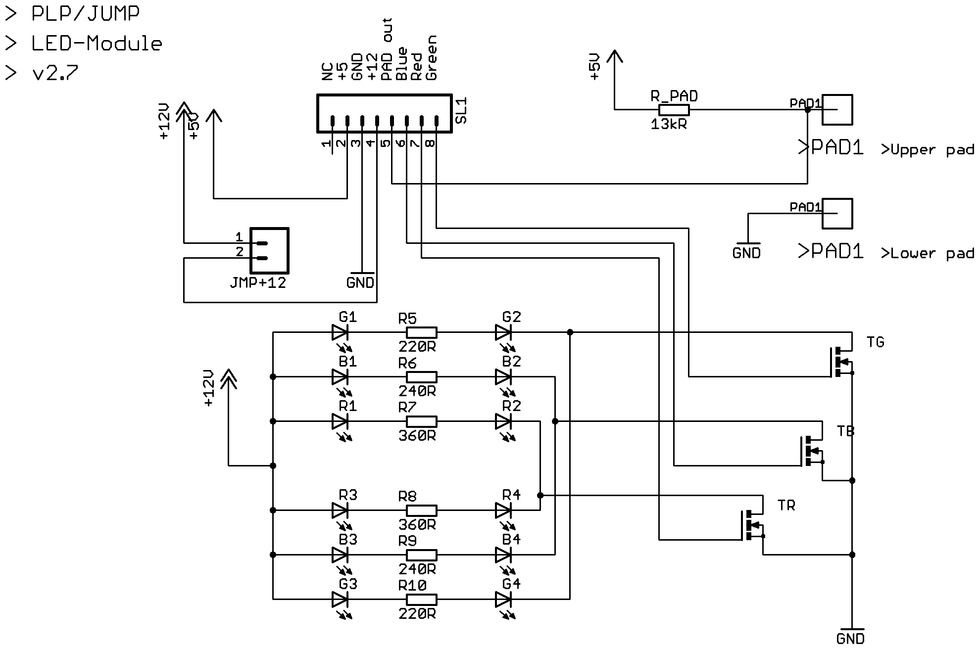

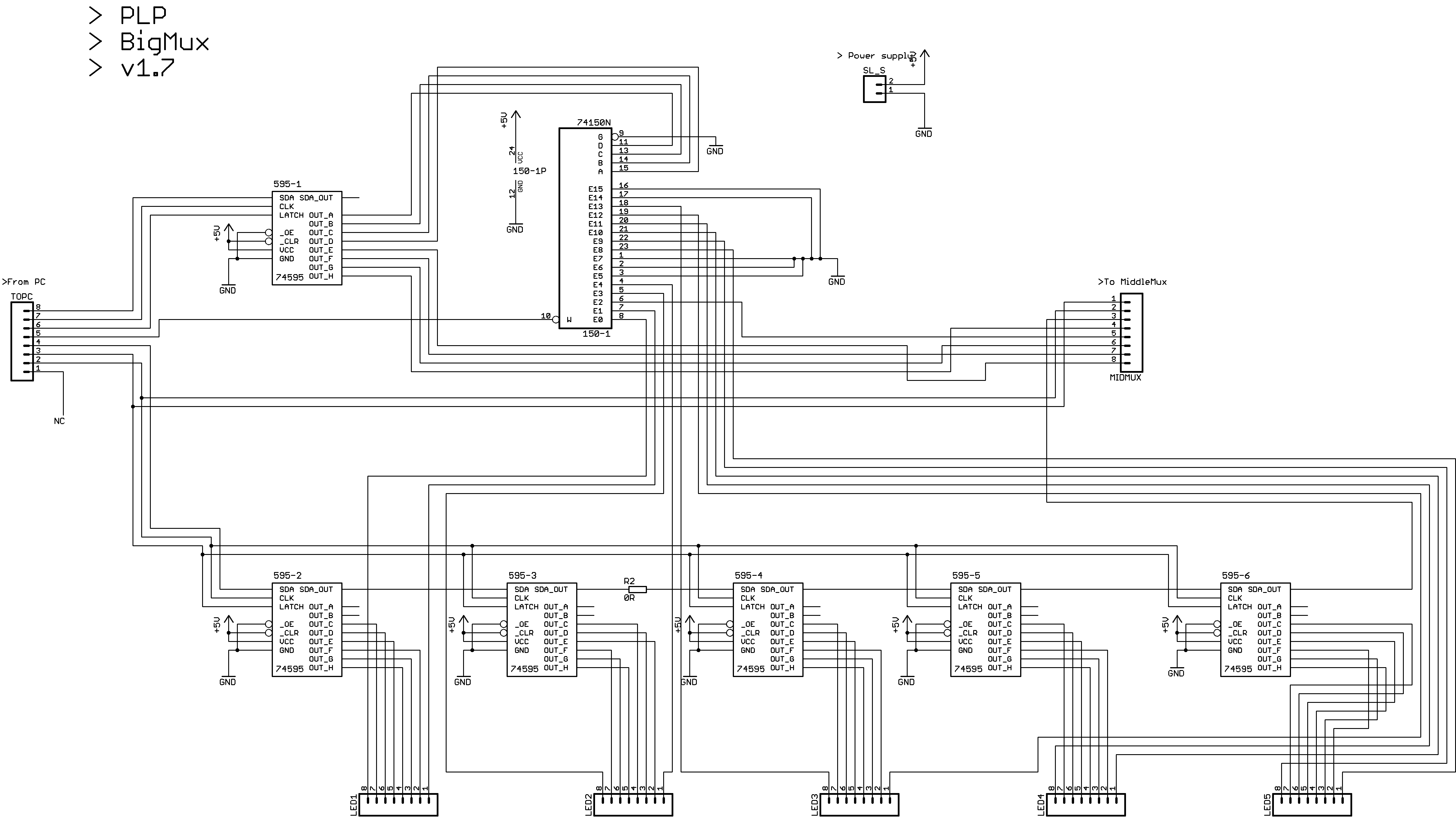
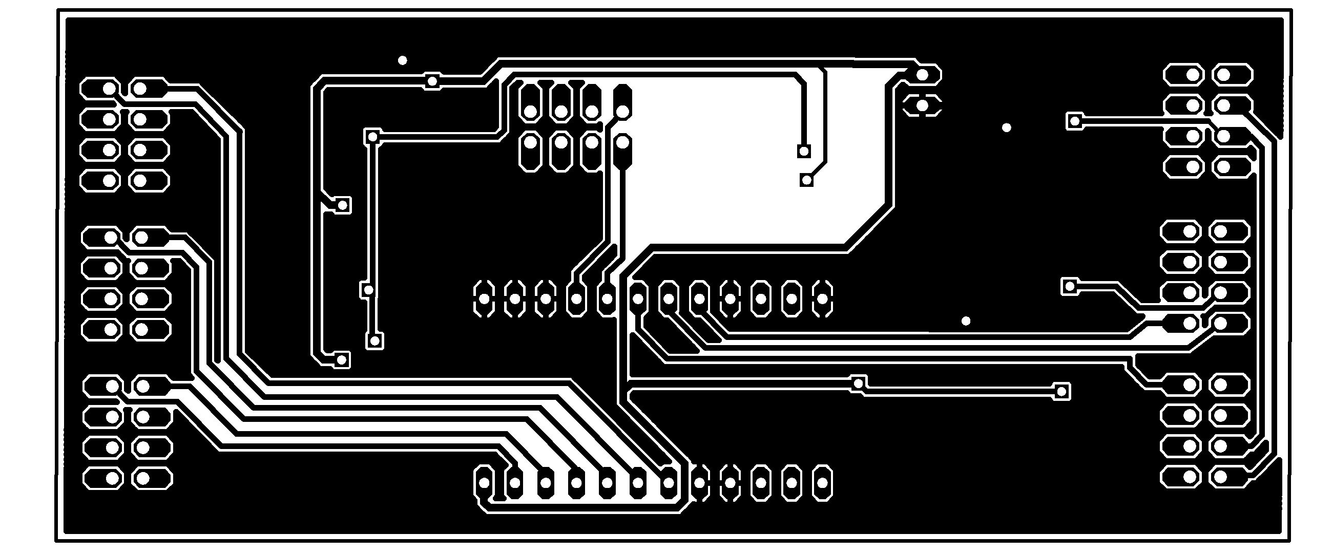
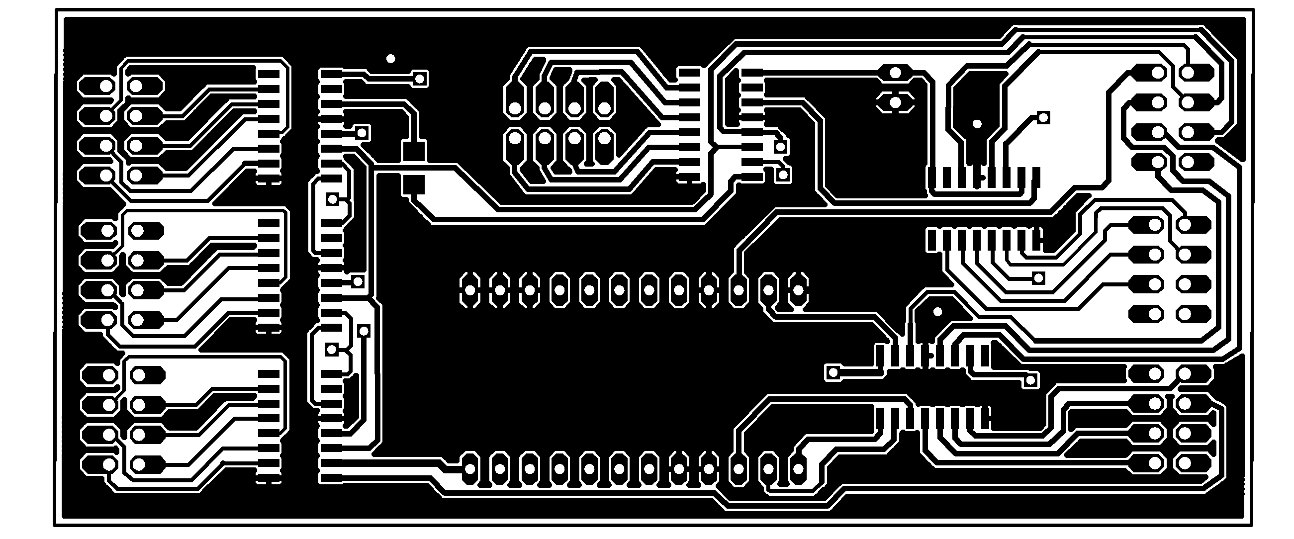
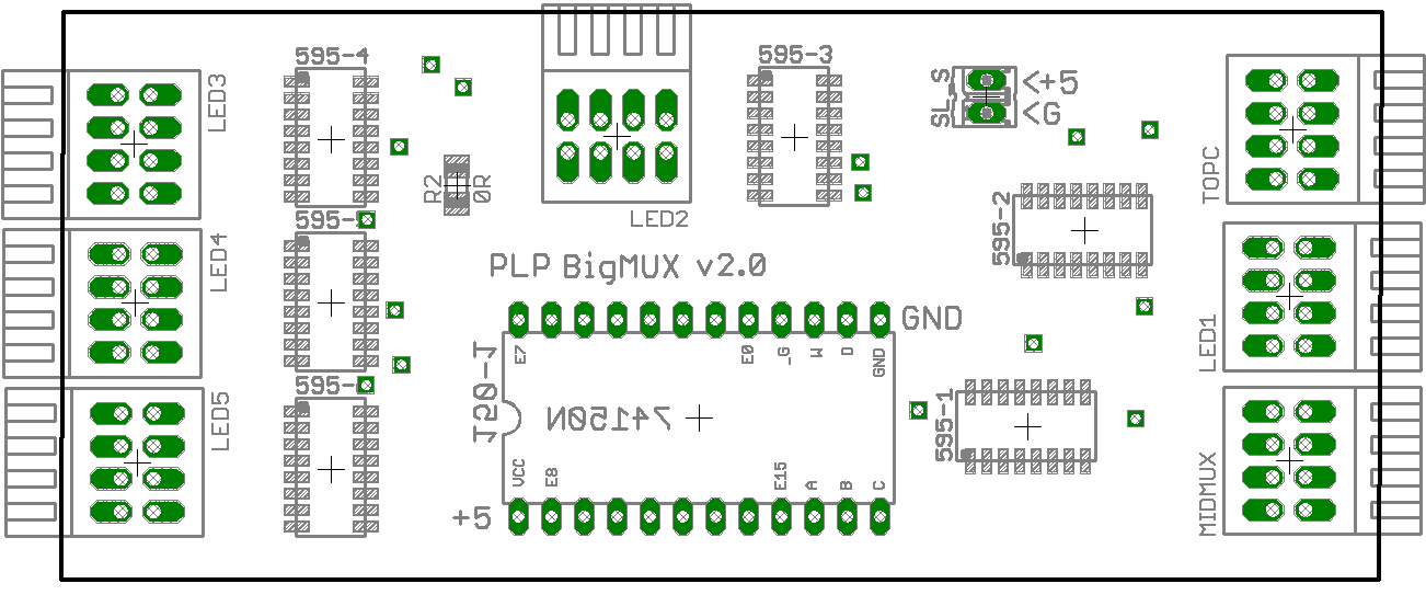
Each subfloor of 25 cells were controlled from three PCBs worth of 74595 and 74150. "BigMUX" and "MidMUX" took 10 cells each and "SmlMUX" took 5. They were daisy chained from the parallell port of the PC which ran the game and music.


This is the largest of the PCBs, in terms of number of components. All in all, four subfloors = 56 * 74595 + 8 * 74150 + 72 * 8-pin connectors.
As a character building exercise, cable making should be part of any youth growing up in todays society. Cables for distributing power and control had to be cut to length and soldered with connectors. This is a small subset of them.

Each cell assembly could easily be lifted out of the frame for repairs, diagnostics and replacement if necessary.

The idea with a having subfloor units was that the entire Jump could be taken apart and tucked away, making the case for a convenient solution that every school and hospital could afford and have room for.

Lights on, floating inputs.

Testing top surface so that the opacity and diffusing characteristics are right.

Each subfloor can be tested by itself.

Put together, it's a fairly large dance floor, which is needed as a user should be able to comfortably jump and play around.

Some cell PCBs were not cleaned enough from the solder flux so there were some creep currents so some LEDs were always on.

Using it
Lighting up a few squares, it's clear that there was a big problem with leakage currents, lighting up few cells when they shouldn't.

First show of a working floor to one of the customer representatives, a lecturer from the GIH school of health in Stockholm. The game goal is to touch the lit up cells as fast as possible, and as many as possible. When a touch on a valid cell is detected, the cell "explodes" like seen in the picture and points are awarded to the player.

Tests with two students with Downs syndrome playing a game of hitting as many squares as possible while they temporarily show up. This shows that the physical size of the floor is enough for more than one person. We tried up to four persons, but three is probably the maximum feasible number without too many mid-game collisions.

One of the biggest rewards was seeing how fun they had, and how it really worked in triggering them to play more and more, and thus getting some fun exercise.

Evaluation
Some of the most important take-aways.
What went right
The strong visual stimuli with bright colors and movement really worked in getting the users attention and triggering them to interact with the floor.
The games were well suited in making users move, encouraging wide and fast-paced physical exercise.
The basic hardware design, such as the port expander scheme, worked really well, except for EMI (see below).
What went less right, aka learning experiences
Having most of the interaction vectors as light and pressure on the floor, the users were looking down on the floor very much, increasing risk of injury.
When soldering, cheap low-quality solder flux of a do-clean sort left residue that catered to creep currents to saturate the transistors and light up LEDs even though they should be off.
Long wires with little protection to EMI left the floor vulnerable with resulting flicker of the LEDs. We worked around it, as it was too late and too expensive to redo anything, with higher refresh rate and a full blanking before setting to ensure everything was off for that frame.
To reduce complexity, a decision was made early on to make the floor as dumb as possible and control it from the PC parallell port due to the availability of free open source Python libraries for parallell port control. The parallell port can only source a very limited amount of current, making the floor even more susceptible to EMI with flicker as a result. What we should have done instead was to have each subfloor controlled by microcontrollers and make sure the long wires was not affected by EMI.
Links, contacts
Email me
KTH, The Royal Institute of Technology